Documentation > UserManual
Circuits
The whole simulator is designed to be a modular system allowing any experiment to be simulated. For a basic user these modules are essentially black boxes that simulated some physical process, for example a low pass filter or a cantilever. In the pyVAFM these black boxes are reffered to as circuits, the pyVAFM comes with many commonly used circuits required to simulate AFM experiments as standard, a complete list can be found here .
Channels and initialisation paramaters
Circuits have two main aspects intialisation paramaters and channels, the initialisation paramters are required by some circuits in order to add them to a simulation, an example of this is the spring constnat for the cantilever. Channels are how data is transfered from one circuit to another, circuits have input and output channels which allow data to be transfered into one circuit (Input) and transfered out of a circuit after it has been processed (output). So by connecting one circuits output to another circuits input it is possible to transfer processed data across a simulation. The philosphy behind the pyVAFM is to allow any simulation to be created and this is accomplished by connecting these various circuits together in order to create various kinds of AFM experiments.
Compisite Circuits
Compisite circuits are a special class of circuit that allows users to create complex arangements of circuits and save them in a seperate file. Then this compisite circuit can be added to a input script in the same way as a regular circuit. It also behaves like a regular circuit and has initliasation paramters, input and output channels. So compisiste circuits allow the user to give the illusion of a simple black box despite the complexity underneath in esssense you can think of a compisistie circuit as a black box that is made of other black boxes. Examples of such compisiste circuits would be the aPLL or an amplitude detection system. For a full tutorial on how to build a compisiste circuit please view this tutorial.
Pushing
Since this is a modular system the order of which the circuits is updated can matter, the order the system will update circuits is determined by the order the users add them in the input script. So for example if circuit A is added then circuit B then A would be updated after B. Although what if circuit A depends on the output of circuit B? In this scanario in the first time step circuit A will see circuit Bs default value (which is 0), this can causes issue with your simulation espeiclaly with feedback loops like PLLs. In order to simplfy simulations the pushing system is implemented, if a circuit is set to be pushed (pushed = True) then at the end of each time step it will update its output channel. If we set pushed to false then the simulation will buffer the output values for one timestep, then in the next timestep release the buffer and update the channels. Hence by setting pushed=False, we can add circuits in any order and update them in any order since we are storing the current values. Although by doing this we introduce a time step delay of 1 time step into the simulation, generally this isn't an issue since the timestep for the simulation is in the nanosecond region.
Force Field
The PyVAFM doesn't simulate tip surface interactions but rather employs a force field, this force field must be aquired outside the simulation by various means that will be covered later. So a force field is essentially a 3d (or 4d in the case of kelvin or STM) scalar field the exact format of the force field can be found in the interpolation documentation. In essence this force field describes the tip surface interaction at various points above the surface, so this field is linearly interpolated to allow forces to be found at any point in the field, hence a fairly dense field is required in order to allow accurate interpolation. This force field can aquired many ways but the most commmon is to use Molecular Dynamics (MD) or Density Functional Theory (DFT) to calculate these forces. In both these cases a tip is created in the simulation and places over the surface, the energies and hence the forces can be calculated at this point. So by moving the tip to various differnet points in the simulation the forces at various points above the surface can be calculated and hence used in the VAFM. The details of running a MD or DFT simulation are beyond the scope of this manual, so I suggest you contact your closest theroist who may be able to assist you with running DFT or MD simulations.
Units
The PyVAFM is a unitless simulation so the units are infact definied by the force fields units. So if the distances in the force field are in nano meters then the scanner will move in units of nano meters. Similarly if the units of force are Nano Newtons then the spring constant of the cantilever would be nano newtons/nano meter. When trying to reproduce experimental results the user must take care that the units match experimental ones since it is often that the force fields units and the spring constants units may be different.
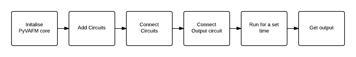
Anatomy of a Simulation
In this section a description of the main components of an input file are described, work flow for every PyVAFM input file will follow more or less the same steps.
Initalise the PyvAFM core
In order to initialise the PyVAFM core the user must first import the Machine class from the vafmcircuits file, this must be done in all PyVAFM input scripts:
Next we must create a class instance of machine in order to execute further instructions
In principle the instance can be called anything but it is common practice to name it machine, if the user names it something else then the instructions shown here must be ammended from machine to the new variable name. Through out this documentation though we will use the variable name "machine" as demonstated above.Finally the dt variable in the Machine class is the time step for the simulation. So by creating this class instance you are initialising the PyVAFM with a time step equal to the value of dt.
Adding Circuits
Next we must add our selected circuits this is done using the "AddCircuit" command, the format for the AddCircuit command is as follows:
Type is the kind of circuit you are adding for example cantilever or waver , a comlete list of circuits can be found here . Name is the user defined name of the circuit, this name must be unique to each circuit you add hence allowing you to add several of the same type of circuit into a simulation. This name is how the circuit will be refered to through out the simulation. Next we have initialisartion paramters for the circuit which are variables the circuit requires to function such examples are rthe spring constnat of the cantilever or cut of frequency of a filter. Since these paramters are unique to each circuit a list of required paramaters can be found in the documentation for that circuit.
Connecting Circuits
Next we must connnect our added circuits, this is done using the "Connect" command, please note it is only possible to connect an input channel to an output channel. The format of the Connect command is shown below :
Where CircuitName is the name the user defiend when the circui was added and InputChannelName and OutputChannelName are the input and output channels respectivally. In order to find a list of input and output channels for a given circuit please refer to the particular circuit documentaion page, on this page you will find a list of channels as well as a description of each. Please note it is possible to connect one output to multiple input, this can be useful for shortning scripts.
Setting up the Output Circuit
In order to get data out of the PyvAFM you must use the Output circuit, this circuit works slightly differnely to most other circuits but follows the same basic principle. It has the following Format:
The main difference is the fact you must make a class instance of the output circuit, here we have used Output this is required for some circuits (Eg: interpolation in order to acess some of the extra commands). Despite this it follows the same pattern as normal circuits, so name is the user defined name of the circuit (You can have multiple output circuits). file is the output file name you want the data to be written to and dump is the rate the file will be written to in units of per step so for example a dump rate of 10 means file get written to every 10 steps. The final part is the register function, this uses the class instance we made before. It follows the same format as connecting circuits where CircuitName is the name of the circuit and ChannelName is the name of the input or output channel. You can as many channels as you want to the register function adn they will all appear as a sepearate coloumn in the output file.
Running the Simulation
The simulation is integrated over time so you must instruct the VAFM to execute for some legnth of time, there are currently two ways of doing this. You can command in the simulation to wait for a given time using the following command:
Where the argument to this functon is the length of time in seconds you want the simulation to wait for. The second way is to move the scanner, moving the scanner circuit takes some finite amount of time and during this movement the simulation will integrate. For a complete list of scanner function please the scanner ) circuit documentaton page
Collecting Output
After the simulation is run for a given amount of time it is a simple matter of collecting your data, this can be found in the output file you specfied in the output circuit. This file is in a coloumn format with each coloumn coresponding to a specific channel that was specified in the register part of the output circuit.
For a simple example of a working input script please refer to Quick Start section or for more detailed examples the tutorials section.
 1.8.9.1