Contain the assembly functions for composite PLL circuits. More...
Functions | |
| def | aPLL (compo, keys) |
| Analog PLL composite circuit. More... | |
| def | dPFD (compo, keys) |
| Digital PLL composite circuit. More... | |
| def | aAMPD (compo, keys) |
| Analogue amplitude detection circuit. More... | |
| def | LockInAmp (compo, keys) |
| Lock in amplifier. More... | |
Detailed Description
Function Documentation
| def customs.aAMPD | ( | compo, | |
| keys | |||
| ) |
Passed a singal throuhg a low pass filter to calculate the amplitude of it.
Initialisation parameters:
- fcut = Cut off frequency for the low pass filter
Input channels:
- signal = incoming signal
Output channels:
- amp = Amplitude of the incoming wave
- norm = normalaised input wave.
Example:
| def customs.aPLL | ( | compo, | |
| keys | |||
| ) |
Assembly function for analog PLL composite circuit. The Phase-Frequency Detector (PFD) multiplies the signals, and the result is passed to a series of lowpass Sallen-Key filters. The mount of filters and their cutoff frequencies are taken from the input parameter filters.
- Note
- For this to work, the output sin should be connected to signal2 in the parent circuit (as shown in example). Also, both signals should be normalised (amplitude = 1) and their offset should be removed.
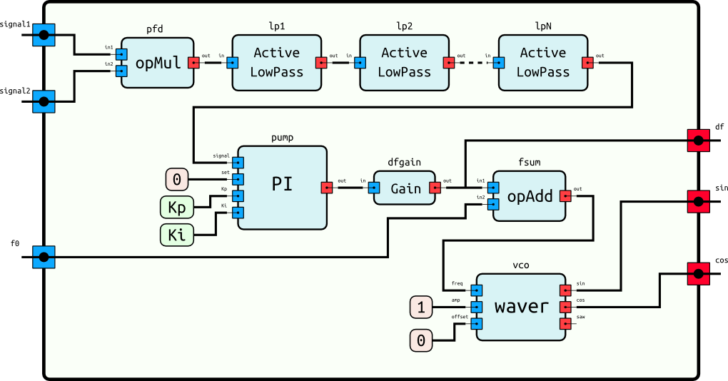
Initialisation parameters:
- filters = list of cutoff frequencies for PFD lowpass filters
- Kp = proportional constant of the charge pump
- Ki = integral constant of the charge pump
- gain = gain on the charge pump output
- pushed = True|False push the output buffer immediately if True
Input channels:
- signal1 = incoming signal
- signal2 = reference signal
- f0 = fundamental frequency
Output channels:
- sin = sine wave of the internal VCO
- cos = cosine wave of the internal VCO
- df = frequency shift from f0
Example:
| def customs.dPFD | ( | compo, | |
| keys | |||
| ) |
Compares the delay between two flip flops becomoing positive allowing frequency shift between two signals to be measured.
- Note
- For this to work, the output sin should be connected to signal2 in the parent circuit (as shown in example). Also, both signals should be normalised (amplitude = 1) and their offset should be removed.
Initialisation parameters:
- fcut = Cutoff frequencies for dPFD lowpass filter
- Kp = proportional constant of the charge pump
- Ki = integral constant of the charge pump
- gain = gain on the charge pump output
- pushed = True|False push the output buffer immediately if True
Input channels:
- ref = incoming signal
- vco = reference signal
- f0 = fundamental frequency
Output channels:
- sin = sine wave of the internal VCO
- cos = cosine wave of the internal VCO
- df = frequency shift from f0
Example:
| def customs.LockInAmp | ( | compo, | |
| keys | |||
| ) |
Calculates the complex phase shift and magnitude of a given signal
Initialisation parameters:
- fcut = Cut off frequency for the low pass filter
- intTime = Integration time of the lock in amp
- CentFreq = the central frequency of the lock in amp signal
- OutAmp = the outputted amplitude of the reference signal
- Gain = gain of the final outputted signal
Input channels:
- signal = incoming signal
- CentFreq = incoming signal
Output channels:
- amp = Complex magnitude of the signal.
- phase = Complex phase of the signal.
- refWave = the reference wave used in the lock in amp, oscilating at the central frequency.
- X = Real part of the complex output.
- Y = Imaginary part of the complex output.
 1.8.9.1